Serial SPI
The SPI bus (Serial Peripheral Interface) is a communications standard, mainly used for transferring information between integrated circuits in electronic equipment. A serial bus, synchronous and works in full duplex mode. Includes a clock line, incoming data, outgoing data and a chip select pin, which switches the operation of the device with which you want to communicate.
el mcp3201http://ww1.microchip.com/downloads/en/DeviceDoc/21290e.pdf
el mcp4822http://ww1.microchip.com/downloads/en/DeviceDoc/21290e.pdf
el mcp1010http://ww1.microchip.com/downloads/en/DeviceDoc/11195c.pdf
el mcp6S91http://ww1.microchip.com/downloads/en/DeviceDoc/21908a.pdf
el mcp23s08http://ww1.microchip.com/downloads/en/DeviceDoc/21919e.pdf
el tc77http://ww1.microchip.com/downloads/en/DeviceDoc/20092a.pdf
son los pdf donde se encontrara informacion detallada sobre el componente en cuestion.
Luego esta la creaccion de estos componentes en el programa capture CIS conectandos a las lineas del microprocesador :


the range of 77 n mcp as positions in the libraries of cis capture by
That left a download file to download it and put it in bookstores:
aceder to you you have to put in google sites and will be able to download entoces when you file the list of files displayed by going to the idquierda and bitter in the sidebar where it says attachments, descargais has library3 name. olb
https://sites.google.com/site/franbc0100/LIBRARY3.OLB?attredirects=0&d=1
Here you have the ace chip77que mcp and failure and are not in the libraries of the capture.
SOURCE ATX.
The ATX is very similar to the AT, but has a number of differences, both in performance and in the voltages delivered to the motherboard. ATX source actually consists of two parts: a primary source, which corresponds to the old AT power (with some additions), and an assistant.

then we find the female and male connectors coupling capacitors:

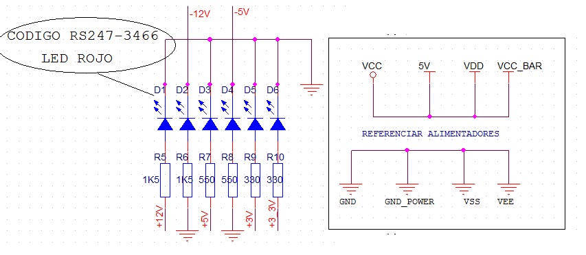
finally the code and the reference LED power and ground for Acers not a mess when land and see the sources of the circuit and the source.

and this is the source in full.
and recently opened to run all the same connections to view them as choose their best and then open the blocks to put together. We must bear in mind that together laas connections have to be exact, as in the schema component then not give us any error.

Save the project:
For what we have here is give the format to pass to the layout and the screen will minimize this scheme, only the circuit diagram display window no Orcad and see that there are 3 open windows in total, including the one just minimized.

Deploy the folder name and select the DESIGN RESOURCES extension *. dsn file to have the same name we have given the project and say that we believe that the NET LIST to use the button.
Now we are asked by an options window some parameters to give the new document in this window select the LAYOUT tab and select the two options which are not default and LAYOUT RUN TO USER ECO PROPERTIES ARE IN INCHES.

The SPI bus (Serial Peripheral Interface) is a communications standard, mainly used for transferring information between integrated circuits in electronic equipment. A serial bus, synchronous and works in full duplex mode. Includes a clock line, incoming data, outgoing data and a chip select pin, which switches the operation of the device with which you want to communicate.
el mcp3201http://ww1.microchip.com/downloads/en/DeviceDoc/21290e.pdf
el mcp4822http://ww1.microchip.com/downloads/en/DeviceDoc/21290e.pdf
el mcp1010http://ww1.microchip.com/downloads/en/DeviceDoc/11195c.pdf
el mcp6S91http://ww1.microchip.com/downloads/en/DeviceDoc/21908a.pdf
el mcp23s08http://ww1.microchip.com/downloads/en/DeviceDoc/21919e.pdf
el tc77http://ww1.microchip.com/downloads/en/DeviceDoc/20092a.pdf
son los pdf donde se encontrara informacion detallada sobre el componente en cuestion.
Luego esta la creaccion de estos componentes en el programa capture CIS conectandos a las lineas del microprocesador :


the range of 77 n mcp as positions in the libraries of cis capture by
That left a download file to download it and put it in bookstores:
aceder to you you have to put in google sites and will be able to download entoces when you file the list of files displayed by going to the idquierda and bitter in the sidebar where it says attachments, descargais has library3 name. olb
https://sites.google.com/site/franbc0100/LIBRARY3.OLB?attredirects=0&d=1
Here you have the ace chip77que mcp and failure and are not in the libraries of the capture.
SOURCE ATX.
The ATX is very similar to the AT, but has a number of differences, both in performance and in the voltages delivered to the motherboard. ATX source actually consists of two parts: a primary source, which corresponds to the old AT power (with some additions), and an assistant.

then we find the female and male connectors coupling capacitors:

and recently opened to run all the same connections to view them as choose their best and then open the blocks to put together. We must bear in mind that together laas connections have to be exact, as in the schema component then not give us any error.

Save the project:
For what we have here is give the format to pass to the layout and the screen will minimize this scheme, only the circuit diagram display window no Orcad and see that there are 3 open windows in total, including the one just minimized.

Choose the one that has a slight resemblance to Windows Explorer.

Now we are asked by an options window some parameters to give the new document in this window select the LAYOUT tab and select the two options which are not default and LAYOUT RUN TO USER ECO PROPERTIES ARE IN INCHES.

Press OK and will tell us that we have created the net list file from DSN described above, we accept and we can exit this program.
No hay comentarios:
Publicar un comentario