OrCAD Capture CIS is a software tool that is used for schematic capture circuit. It is almost identical to the similar tool OrCAD. The difference between the two tools presented in the addition of information system components (CIS). The CIS component information links, such as printed circuit board trace data packet or performance of simulation data, with the circuit symbol in the diagram. When exporting to other tools of the OrCAD design suite, the data stored in the CIS is also transferred to the other tool. So when a design engineer of exports from one scheme to the usefulness of the circuit board layout, most of the circuit elements have traces linked to games.This saves time for the design engineer.
. Has the ability to export netlists, OrCAD simulation utility, allows fast simulation with data representing the circuit will behave. You can export a hardware description of the schematic circuit is currently open.
To understand what is best to create a plate before the plate but we have to create the schematic of the plate, we went to capture environment.
we went to Orcad capture cis icon and we will see a screen like this
The capture toolbar is movable ie you can select an area between buttons and drag it to a new location, resizable, show little support for each tool.


Well, now select File-> New-> Projec
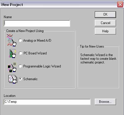
We give a name to our project in the Name field, select the option SCHEMATIC and finally the place where we store all files in the scheme, we give OK and everything ready, we will see the final screen where our scheme took shape, ie something.


I leave the datasheet of pic that once seen will be time to create it:
https://sites.google.com/site/franbc0100/18.pdf?attredirects=0&d=1
to create information especificsa have to give that party, as the name of the party. If the device is a multi-part package, you can specify how many parts make up the package and if the party is homogeneous or heterogeneous. Once we give this information, we draw the part and place the graphics and the pin.
To define a part in the project manager, select the library you want to add the new party. In the menu that appears by right mouse button, select New Part. Box will display the New Part Properties dialog.

once created the pic you put specific names and the number of pins:

hierarchical ports, connectors output page, bookmark DRC, Bookmars, occurrences of parts (including hierarchical blocks), disconnection occurrences (including connections within a bus), occurrences of pin block occurrences editoojas calculation titulos.El looking Browse design around the selected objects, then shows his propiedades.Cada property appears as a header of a column in the worksheet calculo.Cada row is an object located by the publisher.

 we can open this screen:
Part |
to restrict the list of parties and then click Ok. Valid characters for wildcards are an asterisk (*) replacing multiple characters, or a question mark (?) replacing a single character. The names of all parts in the selected libraries that match what typed, will appear in the Part list box. |
sure of the exact name, you can enter wildcard |
Part list |
selected libraries that match the name
introduced in the Part text box. If more than one
selected library, the name of the party will be followed
a slash (/) and the name of the library that
contains. When you select a part of the list, the
name is displayed in the Part text box, and graph
displayed in the preview box.
Libraries |
All parts of the selected libraries that
match what is written in the text box party
Part displayed in the list. To select more than one
library, strike while the mouse is clicked.
Part Search |
| Dialog box opens Part Search, so you can search for a part in all libraries listed in a particular directory. |
Graphic |
Normal or Convert. Some parts have a
Convert presentation to be used for example for
DeMorgan equivalent of a party.
Packaging |
Parts per package indica el número de |
partes que conforman el encapsulado que está editando. |
Part indica qué parte de un encapsulado con múltiples |
partes se está colocando. |
Preview box |
| select. |
Add Library |
Once you know that we prepare for the wiring in the pic along with all the connections that will be taken to dig it the same way, for we can work with bus connection or cables, for connecting multiple cables is better a bus and take it to a label, which is

 what we do from now on for better visualization and control of design.
Once the bus wirings and cables or lines
Ports can be placed in hierarchical folders
schemes sons after the port name so
that connect to the pins of the same hierarchical
name in hierarchical blocks on pages
Schema Schema folders parents.
 |
hierarchy of the same name, and output connectors
page of the same name, Schema pages
within the same chart folder.
The hierarchical ports are stored in the library CAPSYM.OLB.


The connectors are used for cable termination (connector assembly in place of cable). There are different types of connectors in telephone systems, data transmission and computer network connectors most commonly used are the RJ-11 (phone), RJ-12 (phone) and RJ-45 (computer) . The designation "RJ" refers to configurations generally referred to USOC, "Order Codes Universal Service (Universal Service Ordering Codes) and means" registered jack "(Registered Jack).


A potentiometer is a resistor that you can vary the resistance value. Thus, indirectly, you can control the intensity of power supply by a line if connected in parallel, or the difference of potential to do in series.

A party consisting show pic is the conesionarle posivilidad of RS232 serial communication.

not to worry if we do not know where the wiring can carry a scheme for non-Acerno tiing and so without much complication to make the connection, thanks to arem toolbar commands right, we can create designs that are exposed fter the table above.
Then we will make the creation of LCD display and its connection with the seven segments that comprise the display itself:
A liquid crystal display or LCD (English acronym for Liquid Crystal Display) is a thin, flat screen consists of a number of color or monochrome pixels arranged in front of a light source or reflector. It is often used in electronic devices battery because it uses very small amounts of electricity.
Each pixel of an LCD typically consists of a layer of molecules aligned between two transparent electrodes and two polarizing filters, the transmission shaft each being (in most cases) perpendicular to each other. No liquid crystal between the polarizing filter, the light passing through the first filter would be blocked by the second (crossed) polarizer.
The surface of the electrodes in contact with the liquid crystal material is treated to adjust the liquid crystal molecules in a particular direction. This treatment is usually applied normally consists of a thin polymer layer that is unidirectionally rubbed using, for example, cloth. The direction of liquid crystal alignment is defined by the direction of rubbing.
Before applying an electric field, the orientation of liquid crystal molecules is determined by adaptation to surfaces. In a twisted nematic device, TN (one of the most common devices between the liquid crystal display), the directions of surface alignment of the two electrodes are perpendicular to each other, and so the molecules are arranged in a helical structure, or kink . Because the liquid crystal material is birefringent, light passing through a polarizing filter is rotated by the liquid crystal helix passing through the liquid crystal layer, allowing it to pass through the second polarizing filter . Half of the incident light is absorbed by the first polarizing filter, but otherwise the entire assembly is transparent.

The CRAR will siguinte matrix type keyboard like the phones we have in our homes:
is an input device or devices, in part inspired by the keyboard of the typewriter, which uses an arrangement of buttons or keys, to act as mechanical levers or electronic switches that send information to the computer. After the punch cards and paper tapes, the interaction through the ticker-style keyboards became the primary means for computer input.

PORT CONNECTING RIBBON:
to use the connection for some headers
In programming, it is often referred Headers (translated into Castilian as headers), the set of source files which provides an interface for a specific type of data.
They are usually modules that can include various connections to use any features that there are explicit. Usually include profiles of the functions that are desired connection.

The following will be created in the library itself a serial port chip spi:
the 3204 is a converter chip A / D: ie Dijital analog converter has 14 pins and an MCP consists of asuccessive approximation rejist SAR architecture and a standard SPI serial interface, allowing it to be added to any PIC microcontroller. The MCP3204 tiene4 input channels, low power consumption Applications for the MCP3204 include data acquisition, instrumentation and measurement, data loggers, multi-channel, industrial equipment, motor control, robotics, industrial automation, medical instrumentation inteligentese portable sensors .
https://sites.google.com/site/franbc0100/PERSONAL.LLB?attredirects=0&d=1