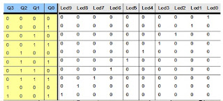
Implement a 4-bit Binary Counter's to permit asynchronous clock and deleted. His departure will be decoded (binary to decimal) on a 10-bar LED's, which will show the account because of its weight, as indicated by the truth table of the decode
In the "Project Navigator" add a new source file, type diagram, which we will call 'deco.sch'.
OPEN PROJECT NAVIGATOR
On your desktop find the icon 'Project Navigator', double click and open the environment with the latest project with which we worked.
CREATE NEW PROJECT
From 'File-> New Project'set the first parameters of the project as the name 'CONTABCD' and type 'Schematic'. We click on 'Next '.
From 'File-> New Project'set the first parameters of the project as the name 'CONTABCD' and type 'Schematic'. We click on 'Next '.
Configure Family, Device, Housing, Speed, synthesizer, simulator and simulation language
ADD NEW SOURCE
We will add a source to our project, with the name 'CONTABCD', using a formal language graphic presentation.
ADDING COMPONENTSWe will add a source to our project, with the name 'CONTABCD', using a formal language graphic presentation.
The first components are going to put a BCD counter called 'CD4CE', a global clock buffer called 'BUFG'and a global buffer set / reset called BUFGSR.
In designs where we need to do a SET, RESET, PRESET or CLEAR to more than one device, we should always use the global internal net SET / RESET low skew. Therefore we should add, to the line to address the global buffer 'BUFGSR' or put the attribute with the name 'BUFG' and value 'SR'.
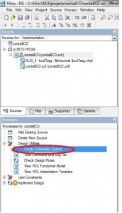
CREATING A SYMBOL OF A MODULE HDL
Before finalizing the design, we have to design the decoder 'BCD-7SEG' in VHDL code, and turn it into a symbol that may subsequently be used in the scheme.
In the "Project Navigator" add a new source file, VHDL module type, which we will call
'bcd7seg'.
It opens a Wizard that will help us generate VHDL code decoder. In the new window
Wizard has named the entity as 'bcd7seg' and uses an architecture of type 'behavorial'.
This step as we finish putting the ports in the entity, ie a bus called 'HEX' with 4 inputs and 7 outputs another bus called 'LED'.
These names do not we put random, but are the names that use the template 'hex2led' ISE ', which will then be added to the architecture to describe the performance of the decoder.
The contents of this file is a template that has defined the organization and lack of defining the architecture that describes the functional operation of the entity.Wizard has named the entity as 'bcd7seg' and uses an architecture of type 'behavorial'.
This step as we finish putting the ports in the entity, ie a bus called 'HEX' with 4 inputs and 7 outputs another bus called 'LED'.
These names do not we put random, but are the names that use the template 'hex2led' ISE ', which will then be added to the architecture to describe the performance of the decoder.
The file will open to us to modify it as the default one decoder is made to a common anode display as is our common cathode display will have to leave it as is shown in the figure below.
Keep the design from 'Project Navigator', generate the command decoder for use in the overall scheme.
The command decoder has been added to the category of symbols, where it can be called.
ADDING NAMES AND MARKS TO THE RED LINE
In the outputs we have placed, manually, OBUF's name to the port's like the name of the segment display and facilitate the study of the simulation.
This done, he throws us a window from which you can configure the time parameters of the simulation. This window we leave the default settings, noting that the time clock high state is
100ns, as in the low state. Moreover, the 'setup time' and 'hold time ' is 15 ns. Here, also sets the clock input (pin chose the 'CLK').
The test time to put it in `2500ns to analyze a full cycle counting.
'HDL Bencher' is open to us within the surroundings 'ISE' showing the waveforms.
In the viewport, we can introduce incentives
FUNCTIONAL SIMULATION ModelSim
Before starting the simulation utility 'ModelSim', add the test bench file to the project by clicking
'Add to Project Test Bench. "This creates a new file format HDL, VHDL in our case, called
'tb_contabcd_tb.vhd'which will be used for 'ModelSim' for the simulation.
Having selected the font 'tb_contabcd-testbench_arch [tb_contabcd_tb.vhd]', press twice on the process' Simulate Behavioral VHDL Model. "
SYNTHESIS OF 4-BIT BINARY COUNTER's
Double click on the process "Synthesize" XST 'situated in the process window and we performed the synthesis of the adder.
SYNTHESIS OF 4-BIT BINARY COUNTER's
Double click on the process "Synthesize" XST 'situated in the process window and we performed the synthesis of sumador.CREANDO RESTRICTIONS (*. UCF)
-----exercise and the download page
https://sites.google.com/site/franbc0100/conteo.jed?attredirects=0&d=1


No hay comentarios:
Publicar un comentario